630m loaded inverted L Antenna
 630m (475kHz) backyard, suburban, wire antenna
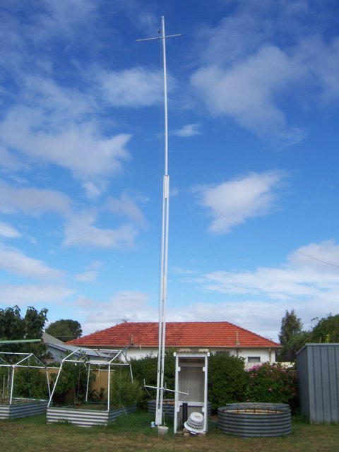
Suburban antenna for 630m.
Again,yes. It is possible to put up loaded antenna for the 630m Ham band in a suburban backyard. As stated before,
if you have a suitably located tree or two and/or a flagpole or like, then go for it. Try to get as much wire
in the air. It doesn't just have to be vertical. A long horizontal component will act as a capacity hat and
help get that current up the wire to where it can be radiated more effectively. It will definitely be better
than a single short vertical wire or mast.
The idea in principal, is to provide additional inductance for an already short antenna and a suitable matching network
to get the maximum power transfer from the transmitter to the antenna.
More wire is better ...
Utilising the three wire capacity hat as opposed to the original single wire, the loading coil had decreased from
about 465uH to about 285uH. Less loading means higher radiation efficiency.
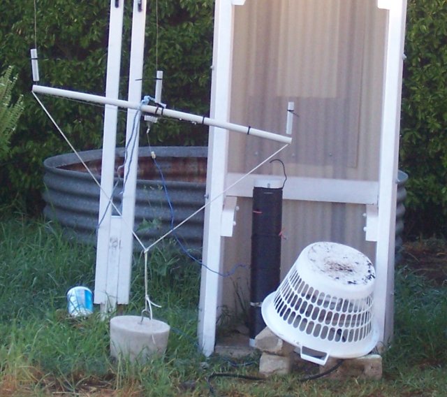
The two outer wires are spaced half a meter (0.5m) from the centre wire. This is the same for both the vertical and
horizontal sections.
The crossarms are pvc electrical conduit with a piece of wooden dowel passing through the centre, to provide
additional rigidity. Three holes are drilled through these arms with which a cable tie passes through and passes through
a black nylon "egg" insulator. Another cable tie is also fed through to provide double reinforcement of the first cable tie.
This acts as a backup in severe weather conditions. This is performed for all insulators on both arms.
The matching unit was derived from a past prototype end fed half wave antenna used on 160m. The 200pF air spaced variable
capacitor was disconnected from the circuit and the remaining coil was then used as an auto-transformer. The coil details
are as follows: 45 turns of 2mm ECW, spaced over 270mm with an air core diameter of 90mm. This is measured to be about 54uH.
The tap point was found to be on the 10th turn from the ground end. This was measured to be 9.3uH.
The loading coil and variometer consists of two windings wound on a 110mm diameter stormwater pipe. 2.5mm2 (7/0.67) electrical
building wire was used. The top part measured to be about 77uH, the bottom section measured to be about 80uH and the rotating coil
was measured to be about 12uH. The inductance will vary as the coil is rotated between the upper and lower coils.
The ground radials consist of 10 various lengths of 2.5mm2 (7/0.67) pvc covered building wire buried about two inches below ground level
and bonded to various metal structures (fence posts, earth stakes, etc.) and all bonded to an earth stake at the bottom of the mast.
There is no guarantee that this design will work in your location. It is merely presented here to show what I used,
because it was simply at hand. Adapt. Recycle. Re-use. YMMV.
Initial 160m design.
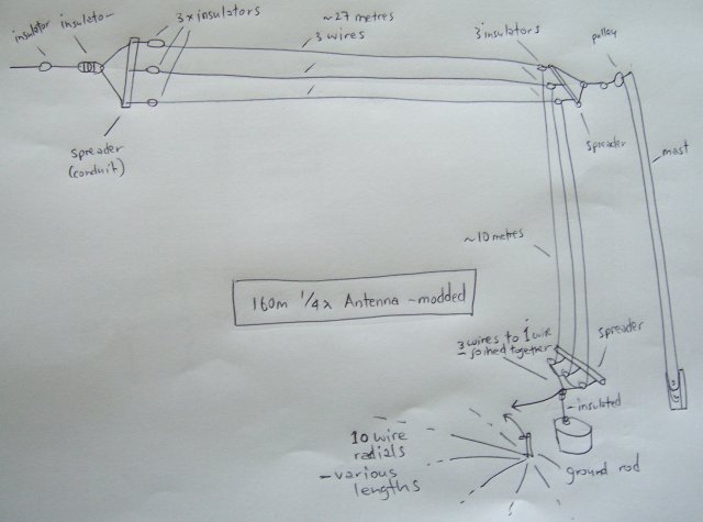
Using the 160m 1/4 λ three wire antenna as a starting point.
Variometer schematic.
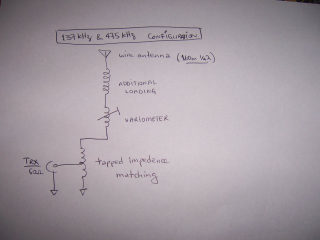
Schematic of the loading and matching circuit.
Loading coil & variometer.
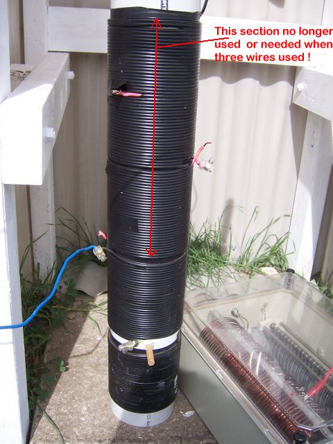
Earlier version when used with single wire antenna.
Latest version.
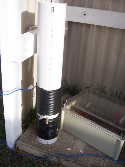
Excess wire removed from loading coil.
Extra ground wires.
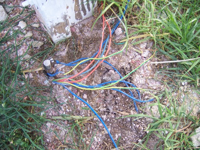
Earth stake with connection of ten buried radials at base of mast.
Testing matching network.
The three wires join here. Testing antenna with loading coil for 630m band.
Useful Links
- A short antenna tuner
- 630m (472-479kHz) Amateur Experimentation VK/ZL